 ar
ar bg
bg hr
hr cs
cs da
da nl
nl fi
fi fr
fr de
de el
el hi
hi it
it ko
ko no
no pl
pl pt
pt ro
ro ru
ru es
es sv
sv tl
tl iw
iw id
id lv
lv lt
lt sr
sr sk
sk sl
sl uk
uk vi
vi et
et hu
hu th
th tr
tr fa
fa ms
ms hy
hy ka
ka ur
ur bn
bn mn
mn ta
ta kk
kk uz
uz ku
ku
compression load cell
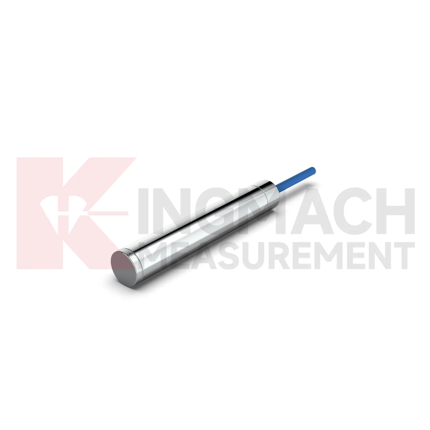
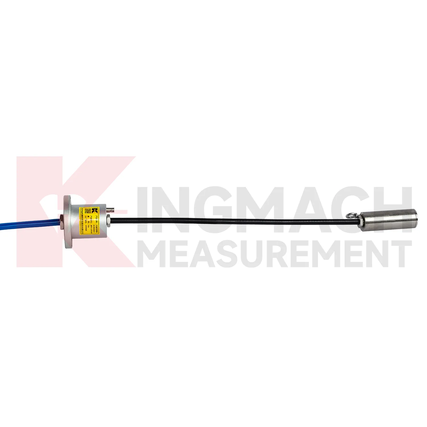
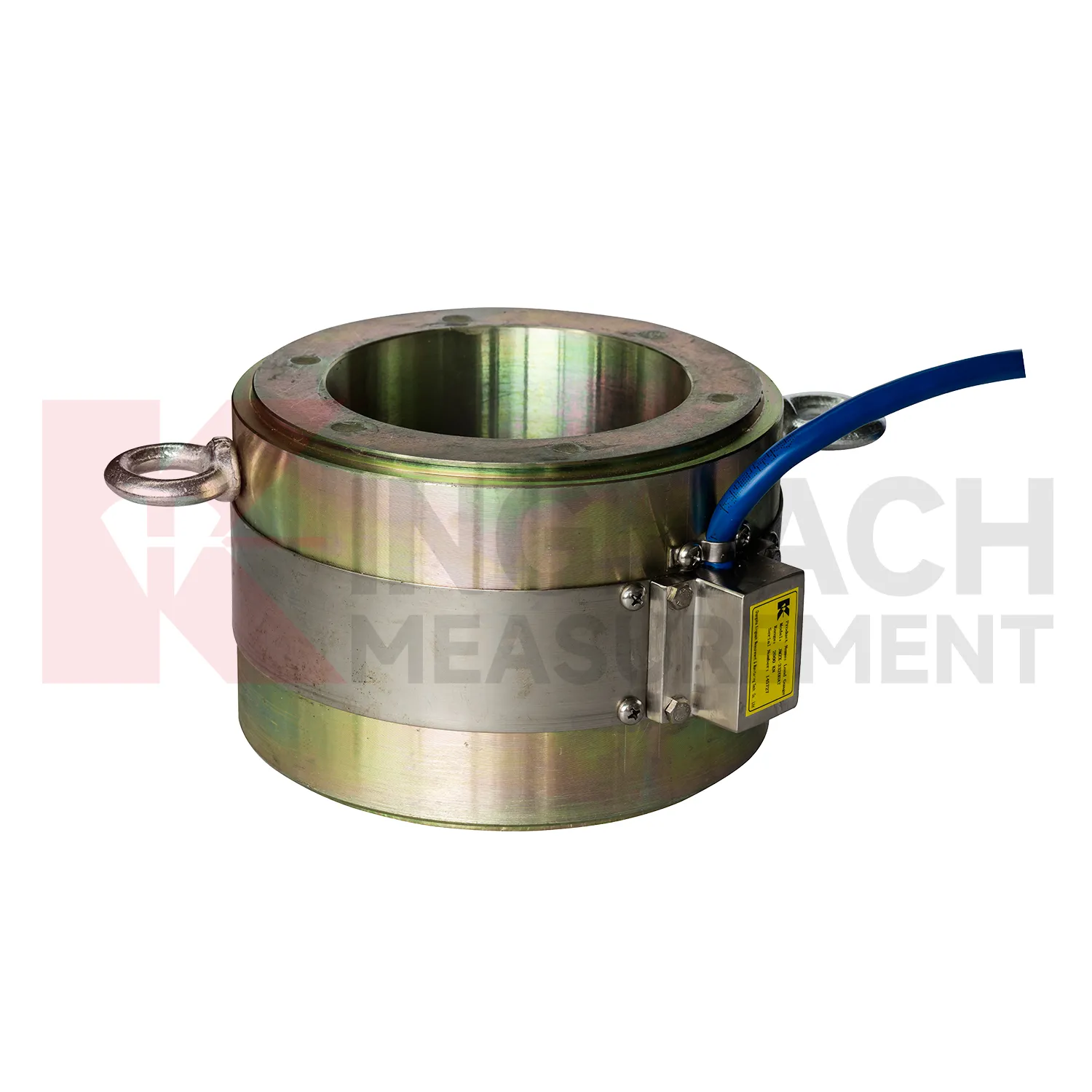
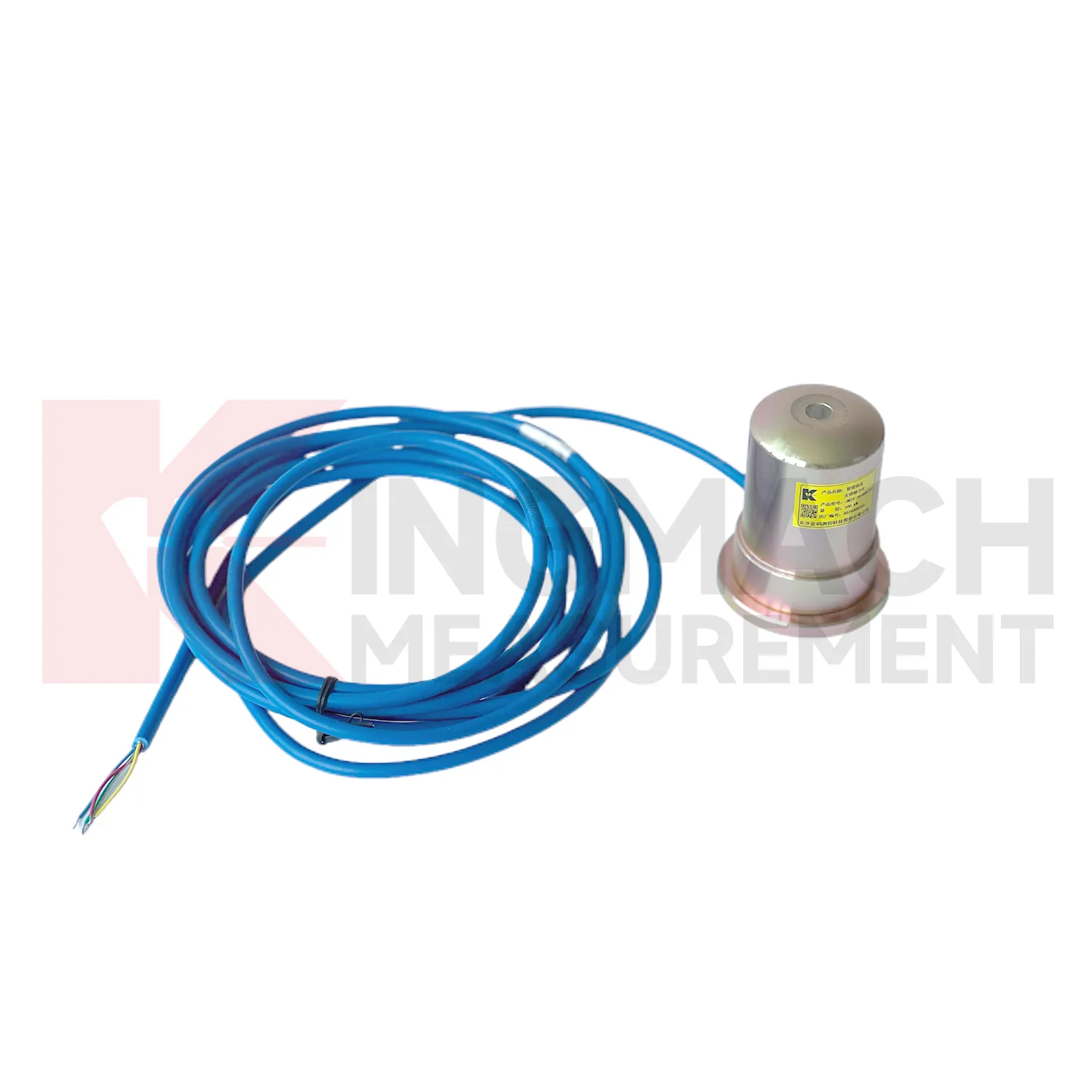
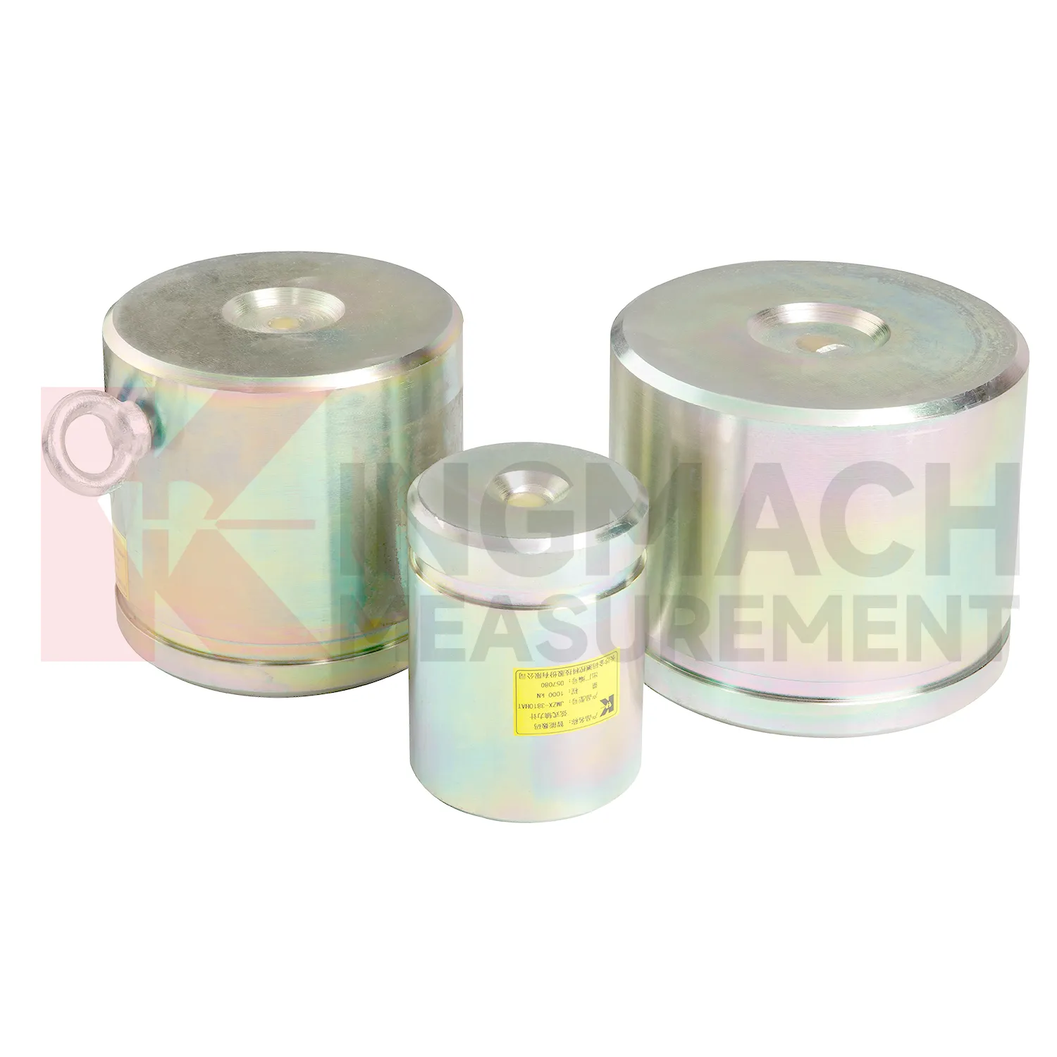
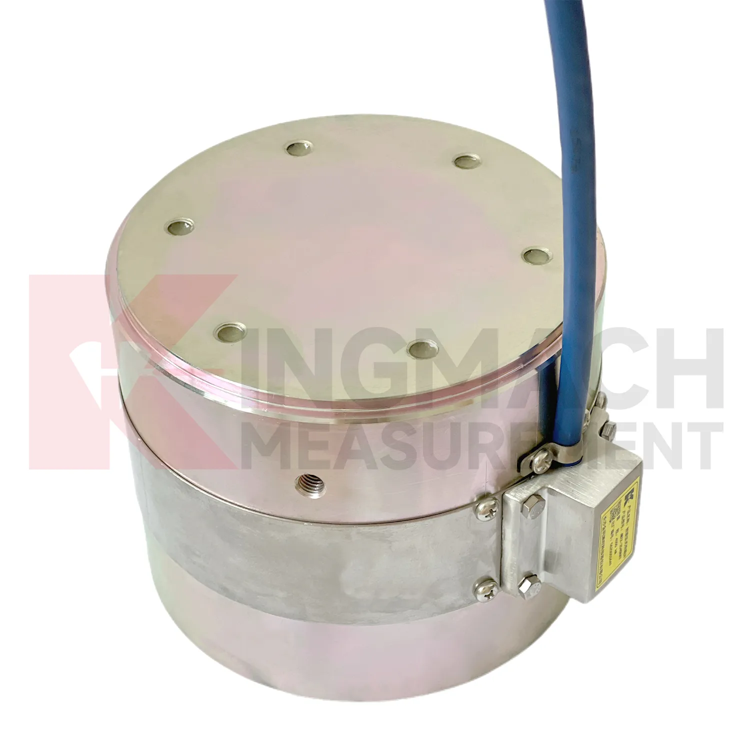
Kingmach compression load cell descriptions should be read together with the data chain around the sensor. A hollow load cell can cover 500 kN to 8000 kN with a long service design, while the solid load cell line reaches 10000 kN with 0.5%FS precision. The axial force meter adds direct kN display and a 1 MPa waterproof rating for support load monitoring. Smart models include memory for calibration information, zero values, temperature data, and stored measurement records. These are not decorative features. They reduce uncertainty when many sensors are installed across a bridge, tunnel, foundation pit, dam, or rail project. Kingmach supplies readouts and data acquisition equipment, so a single instrument can be used for manual reading during installation and later connected to centralized monitoring if the owner requires it. The better specification path starts with the monitored member, expected load range, access condition, waterproof exposure, temperature swing, cable distance, and reporting method, then selects the model around those constraints. Kingmach's after-sales information also refers to warranty service, anti-static and shockproof packaging, and technical response support. Those points are useful in force monitoring because sensor damage, delivery handling, and setup questions can all affect whether the first readings are trusted.
Application of compression load cell
In monitoring networks that cover several structures, compression load cell gives force and pressure points a place beside displacement, settlement, tilt, vibration, water level, and environmental data. The project pain point is interpretation across many channels. A force increase in a foundation pit may be normal after excavation, while a similar increase on a dam anchor after water level change may need closer review. Kingmach smart sensors can store model data, calibration coefficients, zero values, temperature data, and up to 800 records on relevant models. Load ranges across the family include 200 kN to 10000 kN for force products and 0.3 MPa to 8 MPa for earth pressure cells. When connected through readouts, data loggers, DTUs, or software platforms, these points can be reviewed by location and time. Good channel naming, consistent units, alarm thresholds based on design stages, and periodic field checks prevent the network from becoming a pile of disconnected numbers. Large networks also need a naming convention that crews can understand on site. A channel label that matches drawings, physical tags, and software screens prevents mistakes when alarms arrive during night work or bad weather. The platform should keep the raw reading history available, so later reviewers can see whether an alarm came from a real trend or a setup change.
The future of compression load cell
For bridge and cable supported structures, future compression load cell work will likely combine high capacity sensing with digital inspection records. Hollow load cells with 500 kN to 8000 kN ranges and long service design can provide long term anchor or cable force data, while acquisition systems can bring those readings into owner platforms. The technical shift is toward trend based assessment: a cable force value is checked against temperature, traffic, wind, maintenance events, and nearby deformation. Wireless transmission may reduce site visits where access is difficult, although high risk points will still need protected cables, stable power, and field verification. As bridge monitoring requirements become more specific about traceability and response workflow, sensors with stored calibration data and temperature correction will be easier to manage. The most useful future system will not simply send alarms. It will show when the change began, which sensor recorded it, what else changed nearby, and whether the reading matches known structural behavior.
Care & Maintenance of compression load cell
For compression load cell used with manual readouts, care depends on repeatable procedure. Before installation, store the calibration sheet with the instrument and confirm that the readout supports the sensor type. Kingmach product pages mention compatible readouts and comprehensive vibrating wire instruments, which can display force values directly on selected models. During installation, label the cable and channel clearly, record the zero value, and protect the connection point from water and pulling. During each reading round, use the same unit, readout setting, point name, and observation sequence. Note temperature, weather, construction activity, and any visible damage near the sensor. Long term maintenance should include connector cleaning, cable jacket inspection, comparison with nearby points, and periodic calibration planning according to project requirements. If a reading seems wrong, repeat it after checking the cable and readout battery. Many apparent sensor faults come from swapped channels, loose connectors, or missing zero records. Use the same readout settings.
Kingmach compression load cell
compression load cell is often selected after a project team asks where force can change without being seen. In a tunnel, the answer may be the steel support. In a bridge, it may be a cable anchor or bearing. In a foundation pit, it may be a strut, anchor, or retaining wall contact zone. In a dam, it may be an anchor system affected by water level and temperature. Kingmach's monitoring product family allows these points to be linked with settlement sensors, displacement transducers, tiltmeters, piezometers, data loggers, and software platforms. That wider context matters because load change is rarely isolated. A rising force reading becomes more meaningful when it is checked against movement, pore pressure, and construction activity. A falling force reading may point to relaxation, seating loss, or damage near the bearing surface. The instrument gives the first clue, and the surrounding data explains it. It also makes abnormal values easier to discuss with designers, contractors, and maintenance teams.
FAQ
Q: How should compression load cell be selected for a bridge cable or anchor point? A: Start with expected force, lock-off load, possible overload, bearing geometry, and access for later inspection. Hollow load cells are commonly used where the anchor or cable passes through the center opening. Q: What range information is available from Kingmach hollow models? A: The JMZX-3XXXHAT series is listed from 500 kN to 8000 kN, with 0.1 kN sensitivity on the 500 kN model and 1 kN on larger listed models. Q: Why does temperature correction matter? A: Cable and anchor readings can move with temperature, so built-in temperature measurement helps reduce false interpretation. Q: Can readings be stored inside the sensor? A: Smart hollow models list storage for 800 measurement records, including time, temperature, zero values, and correction data. Q: What should be checked after installation? A: Check seating, cable protection, connector sealing, zero value, first stable force, and matching channel name.
Reviews
Michael Anderson
The strain gauges and load cells are extremely accurate and stable. They performed very well in our bridge monitoring project. Highly recommended!
Robert Taylor
The weir flow meter is well-built and delivers accurate measurements. Great value for water management applications.
Latest Inquiries
To protect the privacy of our buyers, only public service email domains like Gmail, Yahoo, and MSN will be displayed. Additionally, only a limited portion of the inquiry content will be shown.
Mia***@gmail.comNetherlands
Dear team, we are interested in your readouts & data loggers compatible with multiple sensors. Do yo...
Olivia***@gmail.comUnited States
Hello, we are currently sourcing high-precision strain gauges and load cells for a bridge monitoring...
Related product categories
- load cell companies
- load cell supplier
- load cells manufacturers
- wholesale compression type load cell
- wholesale force sensor and load cell
- wholesale load cell weight sensor
- load cell rentals
- load cell using strain gauge
- load cell calibration
- load cell wiring
- load cell and strain gauge
- strain gauge and load cell